How To Detect and Prevent Liquid Pump Cavitation?
Almost all liquid systems can be affected by cavitation. It is therefore important to understand the causes and formation of cavitation and to know how to prevent it.
Pump cavitation occurs in a pump or system when there are localized low pressure regions in the liquid, causing vapor bubbles to form and implode. This causes erosion, vibration, and noise and can lead to significant damage to the pump, other parts of the fluidic, and the pumped medium. This affects all positive displacement pumps, including diaphragm, reciprocating, and gear pumps. Cavitation can be successfully prevented by using an optimized pump solution with integrated pulsation dampers in and and by taking appropriate measures to optimize the fluidic system as a whole.
What Is Cavitation and What Causes It?
In fluid systems, pressure gradients vary dynamically depending on the flow velocity and the flow pattern, that is, whether the flow is smooth and continuous or interrupted and rapidly changing. Abrupt changes to the direction of flow (caused by sharp bends, or reciprocating parts) or the geometry of the flow path (caused by sudden changes in cross section or sliding parts) result in more severe pressure drops. In addition, the hydrostatic pressure gradient in the system, such as that created by a supply tank positioned some distance below the pump inlet, further influences the pressure in the system. The resulting pressure losses add up and lead to a significant total pressure drop.
If the pressure in any region of the system falls below the vapor pressure of the liquid, it begins to vaporize, causing cavitation bubbles to form. These bubbles typically occur at the points in a pump where the pressure is lowest, especially where the flow is strongly accelerated or deflected. Cavitation bubbles are then transported further with the fluid flow and thus pass from the low-pressure area into zones with higher pressure. As soon as the local pressure rises above the vapor pressure again, the cavitation bubbles collapse abruptly. These implosions release highly concentrated energy and generate so-called microjets, which can cause strong pressure spikes and extreme temperature peaks. This can lead to considerable damage to the pump housing, the material used, and even the pumped media itself.
What Influences Cavitation?
Cavitation is a phenomenon that is usually limited to the pump. However, the fluidic system on the suction (inlet) side of the pump can have a major influence on whether cavitation occurs and how damaging it is to the pump and fluid. Typically, pressure losses in the suction line have the greatest influence on cavitation behavior. Very narrow and long suction lines can lead to pressure losses that are often underestimated. The same applies to narrow bends, valves, or filters. The pump must compensate for these pressure losses by increasing the suction head, which greatly promotes the formation of cavitation. If the fluid supply tank is located significantly below the pump, this results in a pressure drop at the pump inlet and greatly increases the risk of cavitation.
The individual vapor pressure of the pumped fluid also has an influence on cavitation behavior. A high vapor pressure, as is the case with ethanol, for example, increases cavitation compared to fluids with a lower vapor pressure, such as water. Furthermore, the vapor pressure depends heavily on the temperature of the medium. The higher the temperature, the higher the vapor pressure of the medium, which promotes cavitation. Higher viscosity also increases pressure losses in the suction lines, which further increases the risk of cavitation.
How To Detect Pump Cavitation
Cavitation can sometimes be detected visually by the formation of bubbles in the liquid. The cavitation bubbles (liquid vapor bubbles) usually form and implode in the pump, meaning that they will not be visible even when transparent tubing is used. However, especially in liquids containing surfactants, the agitation caused by cavitation can often result in foaming as dissolved gases in the liquid are released and form bubbles. Acoustically, cavitation can be recognized by a very characteristic crunching noise produced by the imploding vapor bubbles. This can be a clearer indicator, particularly when the cavitation is very pronounced and is not masked by other noises.
Pump Cavitation Affects Pump Performance and Accuracy
Cavitation has negative effects on the entire system, the pump, and the fluid. It reduces the performance of the pump because the higher the proportion of vapor in the liquid, the less liquid the pump can transfer. The pumps in the KNF FP series, for example, have a linear performance curve. This means that doubling the rotational speed also doubles the flow rate. With other pumps, if cavitation occurs, the linear characteristic curve flattens sharply until an increase in the rotational speed no longer causes any change in the volume flow. The occurrence of pump cavitation is particularly problematic in dosing and metering applications, as the accuracy decreases significantly.
What Are the Signs of Cavitation Damage?
Cavitation can cause significant damage to both solid structures and the fluid itself. When vapor bubbles implode near rigid surfaces such as the walls of fluid channels or pump components, the powerful microjets that are created can erode material and leave crater-like erosion patterns. These so-called cavities give the phenomenon its name and can lead to structural damage such as cracks. They occur particularly frequently in sensitive areas of diaphragm pumps, such as valves, valve seats, and the diaphragms themselves. As described below, many other pump technologies are also damaged by cavitation.
Sensitive liquids such as cell culture suspensions or inkjet inks can also be damaged by these implosions. In the case of UV inks, this can even lead to a change in the chemical composition, which impairs quality and function. This phenomenon is known as dark curing.
Cavitation and Outgassing – What Is the Difference?
In addition to cavitation, a phenomenon known as degassing can also occur. When liquids come into contact with gases like atmospheric air, these gases become dissolved in the liquid. At room temperature (approx. 20 °C, 68 °F) and normal atmospheric pressure, one liter of water contains approx. 15-20 ml of dissolved air, according to Henry's law. As soon as this liquid is exposed to negative pressure, air bubbles form spontaneously and very quickly. Unlike cavitation bubbles, these air bubbles do not dissolve back into the liquid when they flow back into areas of higher pressure. These detached air bubbles can significantly reduce the accuracy of pumps like dosing or metering pumps. They can also cause serious issues in applications like inkjet printing or analytical systems.
Cavitation in Centrifugal Pumps
In centrifugal pumps, the greatest risk of pump cavitation typically occurs at the leading edge of the impeller blades, because the fluid is accelerated rapidly there and must flow around the leading edge. Cavitation bubbles can severely damage the blades of the impeller near the leading edge as well as many other areas within the pump, which can lead to pump failure. Severe cavitation also significantly reduces the efficiency and performance of the pump.
Cavitation in Gear Pumps
Gear pumps transfer the fluid through the spaces between the gear teeth from the pump inlet to the pump outlet. On the return stroke, the teeth of the two gears mesh with each other, preventing the fluid from flowing back. When the cavity between the two gears opens, it is quickly refilled with fluid. This creates a deep vacuum, where the pressure is typically below the vapor pressure of the fluid, which can lead to significant cavitation problems, outgassing, or damage to the fluid.
Cavitation in Diaphragm Pumps and Reciprocating Pumps
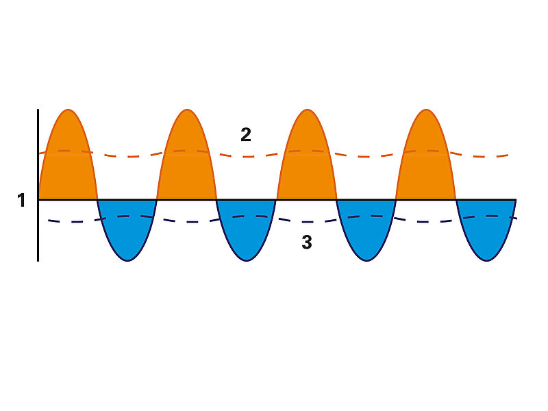
In oscillating pumps such as diaphragm and reciprocating piston pumps, the suction and discharge strokes occur cyclically one after the other.
This cyclic operation causes the fluid in both the suction line and the discharge line to undergo a stop-and-go motion. Due to the inertia of the fluid, this results in pressure pulsations in the pump and the connected lines. During the suction stroke, fluid is drawn from the suction line into the pump. This creates a vacuum, sufficient to overcome all resistance in the suction line and accelerate the fluid to the inlet velocity. During fast suction strokes, the resulting pressure can fall below the vapor pressure of the fluid and cause cavitation. In large pumps, these dynamic effects can be mitigated using pulsation dampers or “air chambers”.
How To Effectively Prevent Pulsation and Cavitation
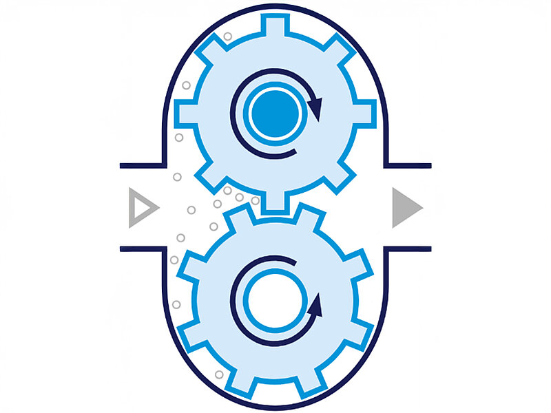
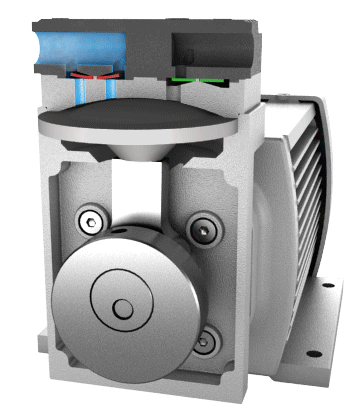
There are various ways to prevent pump cavitation and pulsation. This can be achieved either through the pump itself or through the overall system. For optimization on the pump side, KNF has developed Smooth Flow technology, which is used for example in the FP pump series. The larger of these diaphragm liquid pumps have several diaphragms that work in sequence to produce a smooth, steady flow. In the smaller FP pumps, optimized damping elements are integrated on both the suction and discharge sides. In addition, the flow paths within these pumps have been optimized to reduce pressure drop. As a result, these pumps transfer fluids evenly, continuously, and with low pulsation and virtually no cavitation, ensuring maintenance-free and long-lasting operation.
To prevent pulsation and cavitation in diaphragm pumps without Smooth Flow technology, separate pulsation dampers can be installed directly upstream and downstream of the pump. In addition, operating a larger pump at a lower speed and selecting a smaller eccentric can help prevent cavitation.
Systemic Measures to Prevent Pump Cavitation
To prevent cavitation, it is particularly important to ensure that the pressure loss in the suction line remains low. This can be achieved by taking the following measures:
- Use a suction line with a larger inner diameter.
- Position the pump as close as possible to the supply tank on the inlet side and, if possible, below it. The positive pressure at the inlet reduces the risk of cavitation. In plant engineering, tanks are therefore often placed one floor above the pumps. In systems where the supply tank must be located below the pump, the suction should be minimized.
- Select larger suction-side fittings and valves that are suitable for the application requirements to minimize additional pressure drops.
- Furthermore, the suction line should have as few bends, valves, and fittings as possible with a sufficiently large internal diameter.
From Initial Requirements to the Optimal Pump Configuration
When designing pump systems, KNF's experts ensure that the solution is precisely tailored to the specific requirements of the application. All relevant parameters, such as flow rate, pressure conditions, fluid characteristics, and system geometry, are carefully analyzed together with the customer. The modular design of the diaphragm pumps allows flexible adaptation to minimize pulsation and cavitation. With the help of a powerful and user-friendly simulation environment, fluid lines can be modeled during the consultation phase. This allows critical operating conditions such as the risk of pump cavitation to be identified at an early stage, suitable pump configurations to be identified, and the overall system to be optimized efficiently.