Electrical Options for the Operation of Pumps
Whenever engineers, designers or planners want to operate pumps in a system, they must face the question of how to power and control the pump. An understanding of common electrical connection and control options is therefore useful.
The type of electricity needed for the operation of pumps depends on the type of electrical motor used to drive the pump. Roughly summarized, there are DC and AC electrical options with two common subtypes of AC that can be used to power electric motors and, therefore, operate pumps:
1. Direct current (DC): A unidirectional flow of electric charge that can be generated by an AC/DC converter as well as by power sources such as batteries or fuel cells.
2. Single-phase alternating current (AC or 1φ): This type of current periodically reverses direction and continuously changes in magnitude. It is the most common form of electrical energy used in households and is provided by most wall outlets all over the world.
3. Three-phase electric power (3φ): This is a special type of AC power. It consists of three individual alternating currents or alternating voltages of the same frequency, the phase angles of which are permanently shifted by 120°. It is used worldwide to transfer electrical power via electrical grids and for applications like large electrical motors.
1. DC – Brushed vs. Brushless
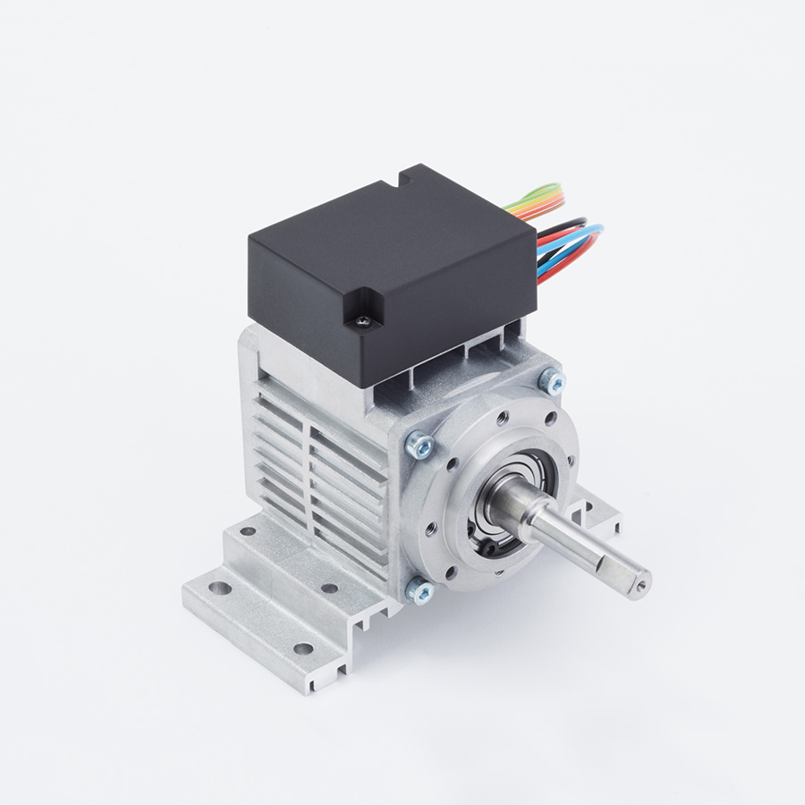
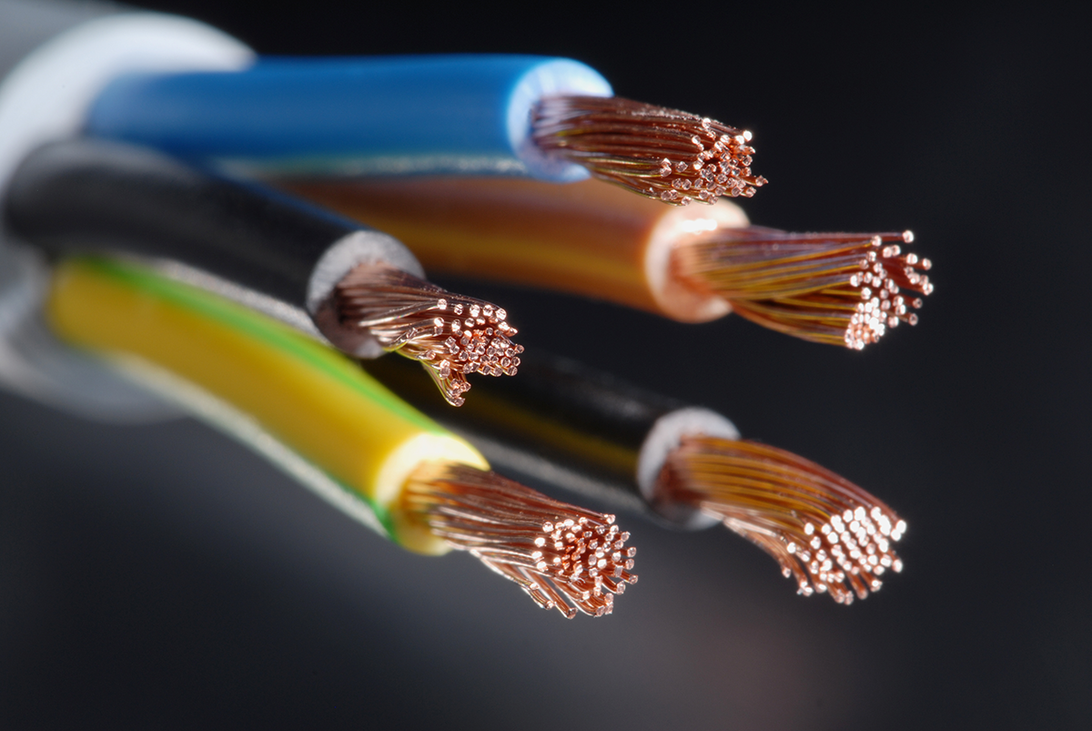
If the application parameters have led to the use of DC electricity, there are several different motor options. A simple and inexpensive option would be brushed DC motors, while the technically most advanced option would be using a brushless direct current motor (BLDC). Most pumps with DC motors can be connected to electricity via two wires, one for the positive pole and one for the negative pole, i.e., grounding. BLDC motors can have additional wires for input, output or for other signals.
1.2 Controlling DC Motors via Supply Voltage
If a pump with a DC motor is to be run intermittently, it can be turned on and off by simply switching power on and off. This is the simplest way to control a pump but might create high loads on the electrical system when the pump is turned on and must work against a restriction. If the pump is to be run at varying speeds, the motor speed can be lowered or increased by adjusting the supply voltage.
However, lowering the supply voltage also diminishes torque and most DC motors come to a standstill when the supply voltage is too low. Also, when starting a pump via increasing the supply voltage, the pump will ‘jump’ into action instead of starting up smoothly. Historically, adjusting the supply voltage used to be a very economical and simple option to operate pumps with electrical motors at different speeds. However, since BLDC motor technology has advanced and prices have been falling, this is no longer the case.
1.3 Sophisticated Operation of Pumps: Using PWM, Control Voltage or UART for BLDC motors
BLDC motors offer more sophisticated control options. Here, the supply voltage remains at 100 % and control can be achieved via a special control signal. This can be a Pulse Width Modulation (PWM) signal, an analog control voltage or a serial digital interface, for example Universal Asynchronous Receiver Transmitter (UART). Which specific signal is used mostly depends on the system in which the pump will operate. All methods offer several advantages compared to controlling a pump via its supply voltage.
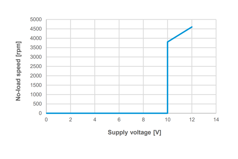
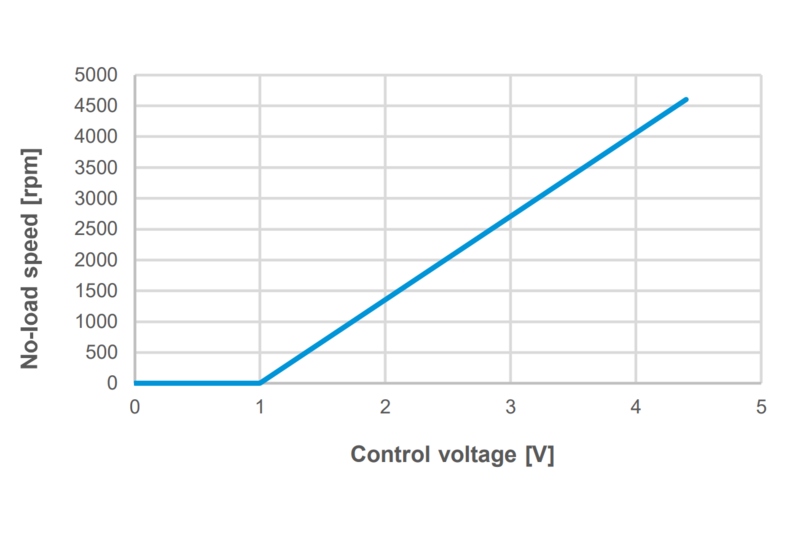
These two graphs show the same 12 V DC motor being controlled via supply voltage (left) and via control voltage (right). While the supply voltage control allows for a range of 3800 to 4600 rpm, the control voltage method allows for a range of 0 to 4600 rpm.
1.3.1 Precise Control and Full Torque to Operate Pumps
Using one of the three methods above, the motor speed can be controlled very precisely. Depending on the exact motor used, this range can cover between 0 and 100% of its running speed. In addition, the motor has a higher torque at lower rpms which is especially important when the pump needs to start against a resisting force such as a vacuum. BLDC motors also offer plenty of other advantages, such as longer lifetime due to fewer mechanical wear parts like brushes.
1.3.2 Communicating with a BLDC motor
As stated earlier, pumps with advanced BLDC motors can be connected with more than two wires. Here, one wire is for the positive pole and one for the negative pole, i.e., grounding – this is the power supply of the motor. Depending on the application, several additional wires can be used for input signals and output signals. With the input signal, users can switch the pump on and off or enter a specific motor speed. Via the output signal, users can receive different information about their pump, such as real-time motor rpm or error information. With this advanced option for the operation of pumps, diaphragm pumps with a BLDC motor can easily become part of a closed-loop system. In addition, BLDC motors allow for advanced digital customization options.
2. AC – Single Phase and Three Phases
Large diaphragm pumps – like those used in process applications – often rely on AC motors. As stated above, there are two common types of AC power: single-phase and three-phase current. Regardless of the AC power used, pumps with an AC motor can normally only be switched on and off. Theoretically, it is possible to operate pumps with a three-phase AC motor via a frequency converter that changes the frequency in which the three phases alternate to each other. However, this must be done via external components and requires in-depth knowledge about the specific motor used and the technical feasibility of letting it run at different rpm. Here, our technical experts are happy to assist further.
75 Years: KNF Celebrates Company Anniversary
A treasure chest filled with memories, facts and stories. Learn more about KNF’s company history.
