
From Observing Bubbles to Helium Leak Testing – An Overview of Pump Leakage Testing Methods
From simple bubble testing to advanced helium leak testing – KNF offers various leak testing methods to meet individual customer requirements.

Pump leakage is always a concern when handling fluids. Depending on the requirements of a diaphragm pump, leakage must be detected and/or quantified using different methods. We present the different pump leakage testing methods and provide insight into their applications, technical advantages and limitations.
1. Different Methods for Different Purposes
As shown in our previous blog post on leakage, leakage is a complex phenomenon. It can occur due to holes or porosity, but also due to permeation. To measure pump leakage and if necessary to quantify the leakage rate, customers can choose from a wide range of test methods. Depending on the measurement method, aspects such as test result, test accuracy and test time can vary greatly. While the most basic tests can only determine whether pump leakage exists at a certain level, some more advanced methods can quantify the leakage rate. This is commonly expressed as lost pressure times volume over time, or in short, mbar l/s.
1.1 Categories of Pump Leakage Tests
Test procedures can be divided into several categories. One way to differentiate is between integral and partial test methods. While integral methods measure the leakage of an entire system, in our case a diaphragm pump, partial methods examine specific sections, such as a pump head, just the diaphragm, the inlet or the outlet connection. Another way to classify test methods is by the test gases used. Some tests use air, while others use special test gases, such as the use of helium in a helium leak test.
2. Basic Pump Leakage Detection
One of the most basic methods of detecting pump leakage is the bubble test. It is used to visualize a local leak, not to quantify the leakage rate. During the test, air flows through the leak from the pump into the environment. This method can detect leaks with a leakage rate ≥ 10-3 mbar l/s. To begin the bubble test, the suction and discharge sides of the pump are connected to the outlet of a pressure control valve. A pressure gauge is attached to the pressure control valve to measure the current pressure. The pressure control valve inlet is pressurized. Before opening the pressure control valve, all points to be tested for leaks are wetted with a soap solution. The pressure control valve is then opened, and the required pressure is maintained for at least 15 seconds, during which the wetted areas are observed for bubbling.
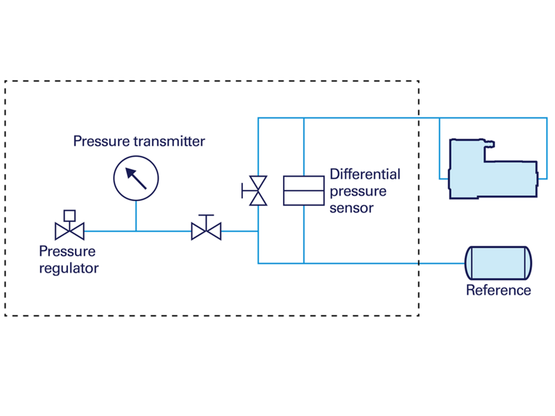
3. How does Differential Pressure Testing work?
Differential pressure testing is an integral measurement method used to determine the leakage rate of the entire pump. Depending on the test setup, the test gas flows from the inside of the pump to the outside or vice versa. With this method, pump leakages with a leakage rate of ≥ 10-3 mbar l/s can be identified. The entire test apparatus, including the reference reservoir, must have a leakage rate ≤ 10-4 mbar l/s.
After pre-checking the test apparatus, the pump is connected to the test apparatus. The pump and reference reservoir are pressurized or evacuated to the same pressure, creating a pressure differential between the entire test system (including the reference reservoir, pump, and pneumatic connections) and the environment. Depending on this pressure difference, test gas would flow from inside the pump and test system to the environment or vice versa.
After a certain dwell time, the pressure difference between the reference reservoir and the pump is measured over a defined test time Δt. With the known volume of the pump Vpump, the pressure changes inside the pump and the test time, the leakage rate of the pump can be obtained. Note that the volumes of the connections to the differential pressure sensor VH and the adapters VA must also be taken into account. The leakage rate of the pump leakage rate is
\(q_L=Δp/Δt (V_{pump}+V_H+V_A ). \)
With diaphragm pumps, the pressure difference across the diaphragm, i.e., between the working chamber and the environment, can cause deformation of the diaphragm. The deformation can depend on the pressure difference. Therefore, the volume of the Vpump may change during the test procedure because the pressure difference across the diaphragm changes. This volume change must be considered when determining the pump leakage rate.
4. Helium Leak Testing – Why Helium?
More advanced testing methods than the two above use special test gases to detect pump leakage. KNF uses helium as a test gas. It is virtually non-existent in the atmosphere naturally, environmentally friendly, inert, non-hazardous and easily detectable, all properties that make it ideal for use as a test gas. At KNF, helium leak testing detects a leakage rate of ≥ 10-6 mbar l/s.
Contrary to what might be assumed, the small atomic and molecular size of helium does not provide a significant advantage for helium leak testing. For diaphragm pumps, the lowest technically feasible leakage rate is 10-7 mbar l/s, which corresponds to a hole size of 10-6 m or 1 µm. For comparison: human hair has a diameter of 40 to 100 µm. However, helium has a molecular size of about 10-10 m, which is several orders of magnitude smaller than the representative hole diameter.
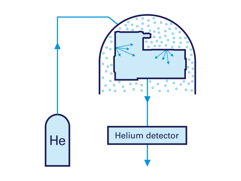
4.1 Vacuum Procedure – Integral (A1 according to DIN EN ISO 20485)
During this integral helium leak testing procedure, helium from the environment at ambient pressure flows into a chamber containing the pump. As a result, the pump is in an environment filled with the test gas. To allow the test gas to flow into the pump, the pump is constantly evacuated, resulting in a lower pressure inside the pump than the ambient pressure. A measuring device analyzes the gas flowing out of the pump for the presence of helium.
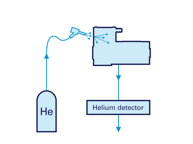
4.2 Vacuum Procedure – Local (A3 according to DIN EN ISO 20485)
This local measurement method focuses on localizing pump leakages and does not determine the leakage rate of the entire pump. To do this, the pump is placed in an ambient environment and is constantly evacuated. Individual sections of the pump are then sprayed with the test gas and the gas evacuated from the pump is analyzed for the presence of test gas. This means that the test gas is entering the pump from the outside through potential leaks.
4.3 Overpressure Procedure – Integral (B3 according to DIN EN ISO 20485)
The integral overpressure method quantifies the leakage rate of the entire pump. It is similar to the integral vacuum method, but the pump is constantly pressurized with the test gas relative to ambient pressure. During the test, the pump is placed in a closed reservoir at ambient conditions. This can be a gas-tight bag or a chamber with a known constant volume. This allows the test gas to flow from the inside of the pump through the leaks into the environment. The gas inside the reservoir is analyzed for the presence of the test gas and its concentration using a sampling probe.
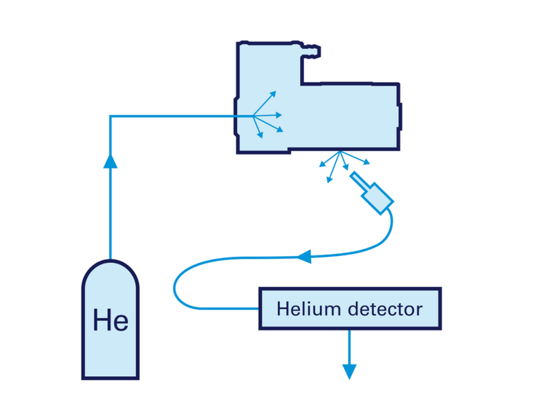
4.4 Sampling Probe Procedure – Local (B4 according to DIN EN ISO 20485)
As with the integral overpressure method, the pump is pressurized with the test gas relative to ambient conditions. Thus, the test gas flows from the inside of the pump to the outside via potential leaks. The environment is an open space, and the pump leaks are localized with a sampling probe placed on different sections of this pump. This allows the leaks to be located but does not measure the leakage rate of the pump.
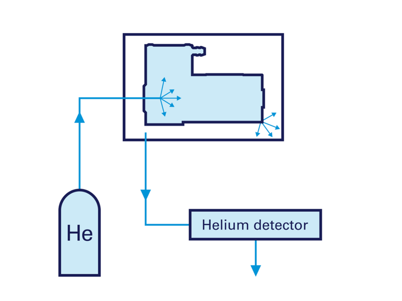
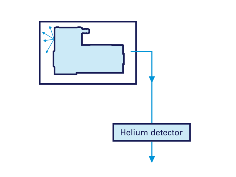
4.5 Vacuum Procedure Enclosed Pump – Integral (B6 according to DIN EN ISO 20485)
This helium leak testing method is similar to the integral vacuum method, but also allows the pump leakage rate to be determined. The pump is pressurized once with the test gas and then placed in a closed chamber. During the test, the chamber is continuously evacuated. As a result, the pressure inside the reservoir is lower than the pressure inside the pump. Therefore, the test gas flows from the inside of the pump into the chamber through potential leaks. The evacuated gas from the reservoir is analyzed for the presence of the test gas and its concentration is used to determine the leakage rate.
5. Which Pump Leakage Test Method Should Be Used?
At KNF, every pump is tested for correct performance as standard before delivery. Depending on the requirements of the pump, additional tests beyond the standard tests may be performed. Pump leak tests are one such optional additional test. For some applications, regulatory requirements may define specific test methods to ensure that a pump is compliant. These methods are also subject to economic considerations, so not every pump is tested with the most thorough methods available. KNF experts are happy to discuss individual customer needs and provide their expertise to ensure that the customer receives the best possible pump with the optimal test procedure.