A Train Analogy: Flow and Pressure Waves in Fluid Systems
Whilst diaphragm pumps offer many advantages, such as durability, dry-running safety, suitability to transport abrasive liquids, etc., in some situations, single-headed liquid diaphragm pumps can cause significant pressure pulsations in the fluid system into which they are incorporated. For this reason, some customers are requiring diaphragm pumps with smooth flow and low pressure pulsations.
Pressure or flow pulsations can have negative consequences in some applications. In inkjet printing, for example, even moderate pressure pulsations reduce the efficiency and maximum flow capacity of the ink delivery system. In systems where the pressure pulsations reach higher pressures, there is an increased risk of more serious issues such as ink foaming and ink starvation which affect print quality. High pressure pulses also have a negative impact on component lifetime and reliability.
KNF has designed a new FP series of low pulsation pumps which provide a much smoother flow delivery, and eliminate the issues described above, even in more challenging applications. The development process of these FP pumps was greatly accelerated by utilizing a new proprietary simulation tool, which can accurately predict flow and pressure variations in fluid systems.
Role of the Pipe in a Fluid System
Understanding the behaviour of pipes is crucial in determining how a fluid system reacts to a pulsating flow, as is the case with single-headed diaphragm pumps, for example. This article shows which physical effects play an important role in the behaviour of pipes carrying a pulsating flow. These effects are:
- Fluid friction (resistance)
- Inertance of the fluid column within the pipe
- Capacitance of the pipe wall
A virtual experiment is presented to help visualize and understand the underlying physics of each effect. The experiment, as shown in figure 1, contains a plasticized polyvinylchloride (PVC-P) pipe having a length l of 1.5 m, an inner diameter d of 4 mm and a wall thickness of 1 mm. The downstream end of the pipe is connected to a reservoir containing water at atmospheric pressure. At the upstream end of the pipe, a piston is placed which will provide a pulsating flow ˜Q to the pipe. Additionally, a steady flow ¯Q is provided to the pipe by means of a separate inlet. Two animated cases of this experiment are shown in video 1 and 2.
We will observe the reaction of the pipe to this steady and unsteady flow combination at the upstream end of the pipe at the location which is indicated with a green dash. At this location, the sum of steady (¯p) and unsteady pressure (˜p) contributions are measured. The ratio between the measured pressure and injected flow at this location, is the hydraulic impedance Z of the pipe, which varies with the stroke frequency n of the piston.


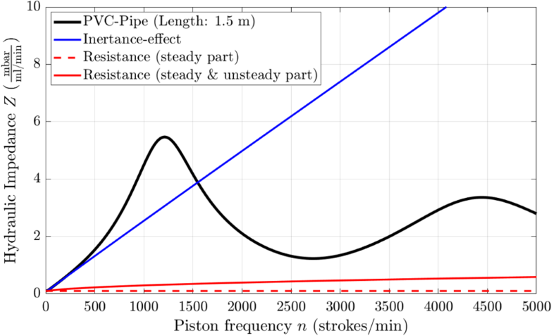
The overall impedance response of the pipe, at frequencies up to 5000 strokes per minute, is shown as a solid black curve in figure 2. This impedance response considers all three effects (resistance, inductance, capacitance) listed above, and represents the actual behaviour of the pipe. Each physical effect will now be investigated separately.
Fluid Friction
Fluid friction or pipe resistance is the first physical effect which is investigated. This effect is caused by frictional effects between the pipe wall and the fluid flowing in the pipe. Two contributions are normally considered for this effect: a steady (continuous) and an unsteady (pulsating) contribution. The physical law which describes the steady contribution is well-known and states that the pressure loss ¯p in pipes for a continuously flowing fluid is proportional to the flow ¯Q in the pipe (Hagen, 1839; Poiseuille, 1841) as long as the flow regime is laminar:
ˉp=128ηld4πˉQ
Where η is the dynamic viscosity of the fluid in the pipe. Thus, the resistance for the steady contribution is constant and not dependent on piston frequency as is shown in figure 2 (dashed red line). Furthermore, one can observe that this contribution is small compared to the actual measured impedance (black curve). Only at zero frequency is the actual impedance curve (black curve) identical to the steady resistance of the pipe (dashed red line). The combination of steady and unsteady friction is shown as a solid red line in figure 2. The unsteady contribution is less well-known and is a frequency dependent, non-linear law which relates pressure loss and flow in the pipe (Zielke, 1968). However, as can be seen in figure 2, the combined resistance effect is still small compared to the actual measured impedance of the PVC-P pipe, for most piston frequencies.
To help visualize these fluid resistance effects, a good analogy is a fast-moving train travelling on a straight track. Imagine first, the train travelling at a constant velocity – the air surrounding the train causes friction: this is a steady force that the engine of the train must overcome. Then imagine the train driver accelerates and decelerates the train in a small but harmonic manner: this will cause an additional unsteady friction effect.
Fluid Column Inertance
In this section, only effects related to the mass of the liquid column within the pipe are considered. Effects that are related to a mass are called inertial effects. Using the train analogy, which was introduced above, this effect can be visualized quite easily. It is assumed, that the train moves back and forth in a harmonic oscillatory manner on a straight railway track. If the train moves slowly, the torque which must be provided by the engine is small. However, more and more torque is needed, as the oscillation velocity of the train is increased.
Similarly, this is true for the pressure built-up in the experiment as shown in figure 1. If the piston has a low oscillation frequency the pressure built-up in the pipe is small. If the oscillation frequency is increased, however, the pressure increases proportional to the applied frequency. The resulting impedance for such a situation is shown as the solid blue line in figure 2. Surprisingly, the inertance effect causes much higher impedance (or pressure pulsations) than the resistance effect. Furthermore, one can observe that for low piston frequencies, up to 500 strokes per minutes, the actual impedance curve and the curve which represents the inertance effect in the pipe match quite well. For larger piston frequencies, however, the differences become larger and the blue linear impedance curve cannot represent the true non-linear impedance of the PVC-P pipe represented by the black curve. So, there must be an additional effect which causes this special behaviour of polymer pipes.
Pipe Wall Capacitance
The characteristic non-linear behaviour of pipes, represented by the black curve in figure 2, can only be explained if the elasticity of the pipe wall is considered. The important fact is, the pipe wall expands and contracts by a small amount, and thus, a certain amount of fluid is either stored or released by the pipe wall, depending on the pressure at that location in the pipe. Therefore, this effect is called a capacitance effect, because one can imagine that the pipe contains an array of small capacitors distributed evenly along the pipe.
Again, the train analogy can be used to explain this capacitance effect which shows a strong interaction with the inertance effect, described in the previous section. Imagine again, the train consisting of a locomotive and several carriages on a straight track. This time however, instead of using a rigid coupling between the carriages, an elastic connection like a spring or a rubber band is used. Now the locomotive starts moving back and forth in an oscillatory manner. For low frequencies the carriages move synchronously (in phase) with the locomotive and the behaviour of the train is similar to the situation when the coupling between the carriages is rigid. If the oscillation frequency of the locomotive is increased, the carriages and the couplings start to interact with each other, and the movement of the locomotive and the carriages becomes asynchronous. Such a situation is shown in video 1, which represents the same experiment introduced in figure 1, but with a piston frequency of 1200 strokes/min.
The green stars indicate the oscillatory part of the movement of fluid particles at the beginning, middle, and end of the pipe. If you observe the first star (the locomotive) and the last star (the last carriage of the train) – one can observe that the movement of the particles at these locations is asynchronous (out of phase). In this special case, the phase difference between the first and the last fluid particle is 90°. Furthermore, the pressure distribution along the pipeline is visualized as dilation of the pipe wall. For the selected piston frequency in video 1, it can be observed that the motion of the pipe acts against the piston and therefore the impedance value at 1200 strokes/min and the pressure pulsation, as shown in the green curve in video 1 is very high and much greater than the combined effect of only resistance and inertance.
If the piston frequency is further increased, it is possible that as the locomotive moves back-and-forth, the last carriage of the train will move “forth-and-back” (180° out of phase). Such a situation is shown in video 2, where the piston frequency is 2700 strokes/min. Observing the first star (the locomotive) and the last star (the last carriage of the train) – one sees that the movement of the particles at these locations is exactly 180° out of phase. Again, the pressure distribution along the pipeline is visualized as dilation of the pipe wall. In this special case, it seems that the pipe acts with the piston and therefore the impedance value at 2700 strokes/min, and the pressure pulsation at the pipe entry shown in the green curve is significantly reduced (compared to the result at 1200 strokes/min).
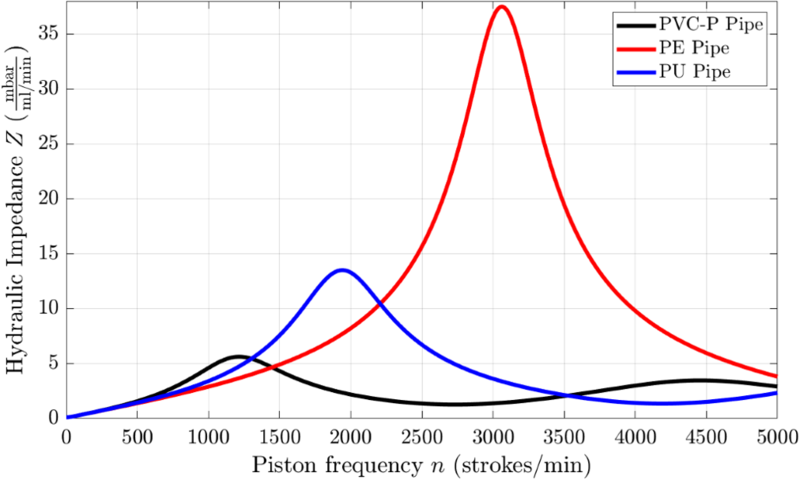
These two special cases clearly illustrate how pressure and flow waves are created in the pipe and interact with the piston. These wave phenomena are the reason for the special shape of the impedance curve, as shown in figure 2. The shape of the impedance curve depends strongly on the material properties of the pipes, as can be seen in figure 3 for the pipe materials: Polyethylene (PE), Polyurethane (PU) and PVC-P. These material properties can be obtained with a special measurement method which has been developed at KNF (Frey et al., 2020).

Transfer to a Real Pump Simulation
Although the polymer pipe behaviour as shown above seems to be quite difficult to capture, it is only one step towards a complete fluid system simulation containing diaphragm pumps. Additional interactions between the upstream pipe and the pump, interactions with the downstream pipe and the pump and the whole pump behaviour must be considered for a complete system description. Such a simulation tool has been developed at KNF and is used to design new pumps, as will be shown in one of the following posts on the KNF blog. Furthermore, this simulation tool can be used to analyze KNF pumps in customer systems, if detailed system information is available. The knowledge about the hydraulic impedance of pipes, however, already shows the great potential which lies in pumps providing a smooth flow. For a continuous flow with zero flow pulsation the pipe impedance is minimal (see the dotted red line in Figure 2) and is identical to the pipe resistance which can be calculated easily. For non-smooth flows, the impedance of the pipe changes with frequency and the error when only considering the pipe resistance to estimate the system impedance can be quite large, as shown by the black curve in figure 2 for a frequency of 1200 strokes per minute, for example.
We hope this technical blog helps to understand why in some situations wave phenomena can cause large pressure or flow pulsations in fluid systems. The experts at KNF have a profound knowledge about these situations. If you encounter a problem, do not hesitate to contact the relevant sales center and we will try to find a solution to your case.
References
Frey, R., Güdel, M., Dual, J., & Staubli, T. (2020). Phase and amplitude based characterization of small viscoelastic pipes in the frequency domain with a reservoir–pipeline–oscillating-valve system. Journal of Hydraulic Research, 58(3), 460-470.
Hagen, G. (1839). Ueber die Bewegung des Wassers in engen zylindrischen Röhren [About the movement of water in narrow cylindrical pipes]. Annalen der Physik (46), 432–442.
Poiseuille, J. L. (1841). Recherches expérimentales sur le mouvement des liquides dans les tubes de très-petits diamètres [Experimental research on the movement of liquids in pipes with very small diameters]. Comptes Rendus de l’Académie des sciences.
Zielke, W. (1968). Frequency-dependent friction in transient pipe flow. Journal of Basic Engineering, 90 (1), 109–115.
75 Years: KNF Celebrates Company Anniversary
A treasure chest filled with memories, facts and stories. Learn more about KNF’s company history.
Anniversary Blog


